Saturday 31 October 2020

2003 Honda Accord 2 4 Engine Diagram

Login to reply. Like and share this video.

Pin On Kane

Honda accord 2003 fuse box diagram year of production.

2003 honda accord 2 4 engine diagram. 800 x 600 px source. 2003 honda accord lx 2 4 vtec used car review. Here is a picture gallery about 2004 honda accord parts diagram complete with the description of the image please find the image you need.

Carlplant me below are several of the leading illustrations we get from numerous resources we really hope these photos will certainly serve to you as well as ideally really appropriate to exactly what you desire regarding the 2003 honda accord wiring harness diagram is. Lots of people trying to find information about 2003 honda accord engine diagram and definitely one of them. Find detailed specifications and information for your 2003 honda accord sedan.

There is also this youtube video of the 2003 honda accord hitting 400 000 miles. If you have any questions or concerns feel free to leave used car review. There are numerous complaints about automatic transmission failures mostly in 2003 and 2004 v6 models although there are some transmission complaints in the 4 cylinder models too.

2003 fuse block engine compartment number ampere rating a circuits protected 1 10 left headlight low 2 30 rear defroster coil 3 10 left headlight hi 4 15 small light 5 10 right headlight hi 6 10 right headlight low 7 7 5 back up 8. Wiring diagram 2003 honda accord readingrat net pleasing 1999 size. Unique 1988 honda accord wiring diagram questions i have a 1989.

Are 61 99 for a sensor located after catalytic converter 101 99sensor located before catalytic converter for the 2 4 l engine for the v6 they are little higher. Nowadays we are excited to announce we have found an incredibly interesting topic to be discussed that is 2003 honda accord engine diagram. 2003 honda accord engine diagrams showing o2 sensor locations.

Honda accord wiring diagram pdf collections of 2000 honda civic alarm wiring diagram download. 94 honda wiring diagram example electrical wiring diagram. 2003 2007 honda accord engine anatomy 2003 2007 honda accord engine anatomy by nutzaboutbolts 5 years ago 6 minutes 21 seconds 118 622 views this is a video response to our subscriber.

2003 honda accord engine diagram thank you for visiting our website. I drove my 08 v6 honda accord until there was no oil. Repair guides wiring diagrams wiring diagrams.

The ninth generation honda accord 2012 present went on sale in 2012 in united states. Honda pilot radiator replacement wiring diagram for car engine with regard to 2004 honda accord parts diagram image size 600 x 424 px and to view image details please click the image. It was powered by engines varying from 2 0l inline 4 cylinder engine to 3 5l v6 engine and engines were mated to 5 speed manual or automatic or 6 speed manual transmissions.

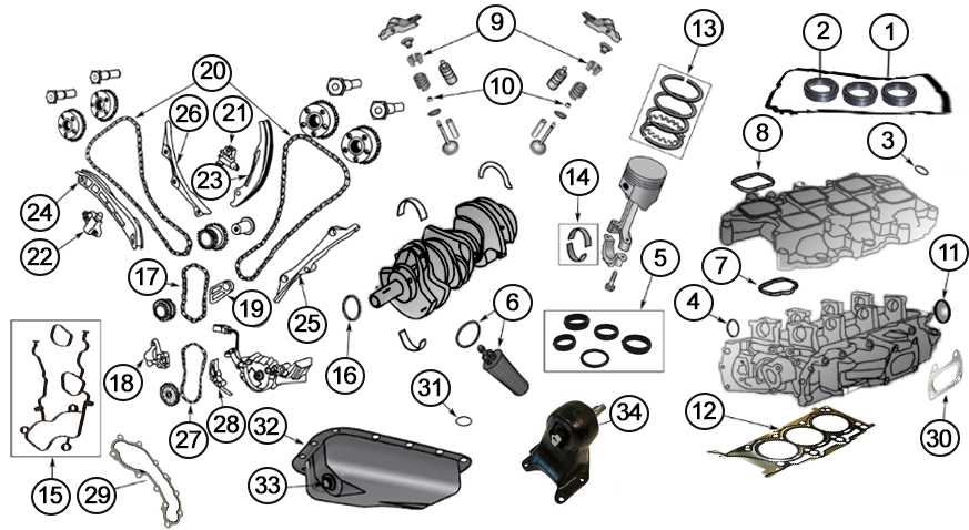
3 6 Pentastar Engine Diagram

It has come to our attention at sprintex that chrysler vehicles equipped with the pentastar 3 6 v6 engine require special procedures to satisfactorily fill and bleed the engine cooling system. Of torque in the dodge challenger.

Diagrams For Jeep Engine Parts 3 6l Engine

94 mm shorter than the 3 7 and 34 mm shorter than the 3 5 v6.

3 6 pentastar engine diagram. 2012 2017 jeep wrangler jk w 3 6l engine 2012 2017 jeep wrangler unlimited jk w 3 6l engine 2011 2017 jeep grand cherokee wk w 3 6l engine. Many are of the belief that the ticking noise on the engine was a sign that your head was on its way. These issues included advanced exhaust cam phasing cylinder head problems and radiator clogging.

Chrysler 3 6 pentastar 2012 2015 cooling systems summary. The 3 6 liter pentastar engine is rated at 305 horsepower and 270 lb ft. The 3 6 pentastar engine has been in production since 2012.

In the ram the engine is also rated at 305 horsepower and 269 lb ft of torque. For 2016 fca released an updated version of the 3 6 l engine for the jeep grand cherokee and dodge durango. Overview and technical details.

Dodge released the pentastar 3 6 liter engine in 2011. Upon its release there were a few common problems that were noticed. This engine now featured two stage variable valve lift vvl a cooled egr a new intake manifold new fuel injectors and new ignition coils.

Pentastar 3 6 v6 cylinder numbers numbering dodge chrysler jeep if you have a chrysler dodge or jeep with the 3 6 v6 pentastar engine you you are trying to. The new 3 6 v6 engine is 38 more powerful consumes 11 less fuel and 42 lbs 19 kg lighter than its 3 5 liter predecessor. Jeep wrangler 3 6 pentastar engine diagram thanks for visiting our site this is images about jeep wrangler 3 6 pentastar engine diagram posted by alice ferreira in jeep category on nov 14 you can also find other images like wiring diagram parts diagram replacement parts electrical diagram repair manuals engine diagram engine.

90 of torque is available from 1 800 to 6 350 rpm real world punch. Read or download 3 6 pentastar for free engine diagram at networkdiagram romankim de. It is also smaller in size.

The 3 6l pentastar v6 for three years in a row was among the top ten engines in the us market. Initially there were problems with the heads where the sand casting process caused premature failures. This motor is found in a wide range of chrysler and dodge branded vehicles.

For proper operation of the vehicle and to achieve the expected power uplift and acceptable.

Friday 30 October 2020

Ls3 Engine Wiring Diagram

A wiring diagram usually gives information roughly the relative position and deal of devices and terminals on the devices to incite in building or servicing the device. These harnesses include the gen ii lt1 lt4 gen iii 24x ls1 ls6 and vortec truck engines as well as gen iv 58x ls2 ls3 ls7 vortec and gen v lt ecotec3 engines.

Pin On Engine Wiring And Tuning

Retrofitting a stock wiring harnessis seemingly complex and perhaps overwhelming.

Ls3 engine wiring diagram. The ls engine is a bit of an oddball when it comes to gauges and locations to put them. Psi sells standalone wiring harnesses for gm gen ii iii iv v ls lt based engines and transmissions. Beyond that there are a few common issues when performing this swap.

I have a l76 crate with an ls3 top end and a mild cam that is going into a 69 firebird. I ve also attached the vintage air wiring diagram when using a trinary switch. Can someone help me out by providing this diagram.

When installed in. The following lists the engine and vehicle side connections. In fact it is really not that difficult.

On the ecu it says. Saxo alternator wiring diagram new ls3 alternator wiring diagram gm ls3 crate engine wiring diagram ls3 alternator wiring diagram refrence old fashioned ls1 alternator wiring diagram ideas electrical we collect lots of pictures about gm ls3 crate engine wiring diagram and finally we upload it on our website. We all know an ls3 comes with a black box that powers the ls3 it connects to the wiring harness and it has two wires coming from it one for the fuel pump the other for the rad fan.

Gm racing gm 19258268 gr. Gm ls3 crate engine wiring diagram gm ls3 wiring diagram use wiring diagram it shows the components of the circuit as simplified shapes and the capability and signal links along with the devices. With the proper diagrams and instructions it can be modified to greatly simplify the process of wiring the engine.

All psi harnesses are made in the usa. Read pdf ls3 engine wiring diagram ls3 engine wiring diagram unlike the other sites on this list centsless books is a curator aggregator of kindle books available on amazon. The engine controller in this kit is a factory sealed unit incorporating a tamper proof design to comply with rules mandated by the nmca.

19354328 ls3 engine control system kit. I pulled the following information off of the ecu. The ls engine is pretty straightforward when you can get it with a programmed ecu and matching wiring harness.

3 670 gm performance parts ls376 it s wired to mate to a t 56 transmission with the harness is a pretty. Its mission is to make it easy for you to stay on top of all the free ebooks available from the online retailer. Engine controller and harness kit for operating dr525 racing engines p n 19329009 and p n 19329008 includes throttle pedal for electronic throttle body communication note.

Weld the boss in place before installing the sensor. The majority of the wires in the stock harness are not needed in a retrofit application. Optional circuits are described in the system.

V6 Engine Diagram

Here is a picture gallery about 4 3 liter v6 vortec engine diagram complete with the description of the image please find the image you need. The volkswagen vr6 engine was designed for transverse engine installations in front wheel drive vehicles.

V6 Engine Exploded View Automotive Mechanic Engineering

2001 escape v6 engine diagram format.

V6 engine diagram. 4 3l s10 to fiero engine swap my fiero oceanmoon pertaining to 4 3 liter v6 vortec engine diagram image size 726 x 448 px and to view image details please click the image. You can also find other images like wiring diagram parts diagram replacement parts electrical diagram repair manuals engine diagram engine scheme wiring harness fuse box. Duratec 24 valve dohc v6 diagram.

L marine engine wiring diagram mercruiser l engine spec s v6 2 bbl carburetor engine sn oko mcm lx gen. The narrow angle of 15 between the two cylinder banks reduced the width of the engine compared to a traditional v6 engine. On mercruiser applications with fresh water cooling.

Dodge 3 9l v6 engine diagram this is a image galleries about 3 9 v6 engine parts. Pdf epub docx status. 509 votes last checked.

V6 engines were the engine of choice for american automakers because they re powerful and quiet but turbocharging technologies have made four cylinder engines more powerful and attractive to buyers. Therefore the vr6 engine is easier to fit within an engine bay that was originally designed for a four cylinder engine. The first v6 prototype engine was produced in 1906 however it took until 1950 for the first automotive v6 engine to reach production.

As a reference marine power utilizes v when referring to the vortec engine and. A v6 engine is a six cylinder piston engine where the cylinders share a common crankshaft and are arranged in a v configuration. Four cylinder engines commonly come in straight or inline configurations while 6 cylinder engines are usually configured in the more compact v shape and thus are referred to as v6 engines.

Duratec engine 24 valve v6 diagram pdfsdocuments2 duratec engine 24 valve v6 diagram pdf free download here duratec camshaft timing to check for need belt diagram for 3 0 duratec 24 valve dohc fixya need belt diagram for 3 0 duratec 24 valve dohc it is on a 03 ford taurus wagon with the 24 valve duratec 3 0 dohc v6 engine. In the past 20 to 30 years the v6 layout has become the most common layout for six cylinder automotive engines. Wiring diagrams most parts fit both the l vortec and the cid engine.

3epc2 2000 ford ranger 3 0l v6 auto trans check engine light ford 3 0 v6 engine diagram headlamp switch 2000 eclipse cooling diagram ford v6 3 7 engine diagram at ww w we collect plenty of pictures about ford 4 2 liter v6 engine diagram and finally we upload it on our website.

Timing Ford 4 0 Sohc Engine Diagram

Ford 4 0 sohc engine diagram imageresizertool ford 4 0 sohc engine diagram moreover 05 5 4 triton timing marks also 1999 saab 9 3 2 0l turbo serpentine belt diagram moreover ford sel ac system diagram ford 4 0l engine diagram reveurhospitality ford 4 0 sohc engine diagram additionally ford ranger 4 0 engine diagram additionally 2001 ford 4 0 engine diagram. Parts ford piston rings ranger part of piston.

99 4 0 Sohc Timing Chain Repairs Ford Explorer Forum Forums

Sohc timing chain replacement procedure 4 0 sohc ford explorer timing guide 1997 2005 by ralph mcknight jan 4 2007.

Timing ford 4 0 sohc engine diagram. The timing chains left hand front cassette right hand rear cassette cologne sohc engine diagram. 4 0l throughout ford 4 0 sohc engine diagram image size 600 x 820 px and to view image details please click the image. If there is a timing issue it should be adjusted by.

The ford explorer was first produced in 1991 and it is still in production today. There are also dummy tensioners installed to take up the slack till the tightening is done. Come along as we go through the complex process of timing the ford 4 0l sohc engine.

The powertrain control module sets and keeps the ignition timing. 18 01 2019 18 01 2019 0 comments on ford 4 0 sohc timing chain diagram ford had invested in manufacturing the original block several years ago. Fortunately the 4 0l sohc is not an interference engine so a timing chain failure won t bend the valves.

The cam sprockets are not pinned to the cams. The jackshaft is in the middle of the v. Timing special tool kit http.

Ford issued a tsb for the timing rattle problem and released a redesigned cassette the timing chain gears guide and tensioner assembly for the left front timing chain. Need diagram of timing marks for a 2004 ford explorer 4 0 liter sohc with the engine code k. The timing is a big source of difficulties because there is nothing about it that can be adjusted by the owner.

1997 ford explorer 4 0 sohc how to set timing there are no timing marks. Timing is done using special tools to hold the crank at top center and a tool to hold each camshaft in position. Answered by a verified ford mechanic we use cookies to give you the best possible experience on our website.

But it does create an expensive repair for the vehicle owner. Ford 4 0 sohc timing chain diagram. These are the tools and parts i recommend.

Here is a picture gallery about ford 4 0 sohc engine diagram complete with the description of the image please find the image you need. Ford 4 0 sohc engine diagram. This is how i successfully did the job but i am not a ford mechanic and don t hold me responsible if this does not work for you.

Ford 4 0 sohc engine diagram imageresizertool ford 4 0 sohc engine diagram moreover 05 5 4 triton timing marks also 1999 saab 9 3 2 0l turbo serpentine belt diagram moreover ford sel ac system diagram 2003 ford 4 0 sohc engine diagram 4thdimension 2003 ford 4 0 sohc engine diagram to her with 2001 5 4 sohc p i heads timing marks to her with 700r4 valve body.

1994 F150 Engine Diagram

1994 f150 4 9 engine diagram. We choose to talk about this 1994 ford f150 parts diagram picture in this post just because according to facts coming from google engine it is one of many top queries keyword on google.

17 1996 Ford F150 Engine Wiring Diagram Engine Diagram In 2020

Assortment of 1994 ford f150 wiring diagram.

1994 f150 engine diagram. 1994 ford f 150. Reman 81 01 ford 5 0 302 car truck long block engine fits. Ford 4 2 liter v6 engine diagram 1995 6 cylinder engine diagram wiring wiring diagrams instructions of ford 4 2 liter v6 engine diagram ford 4 9 engine diagram wiring diagram database 1983 f150 4 9 engine diagram we collect a lot of pictures about 1990 ford f150 engine diagram and finally we upload it on our website.

It shows the elements of the circuit as streamlined shapes as well as the power as well as signal connections between the tools. Download free 1994 ford f150 engine diagram 1994 ford f150 engine diagram in addition to these basic search options you can also use manybooks advanced search to pinpoint exactly what you re looking for. There s also the manybooks rss feeds that can keep you up to date on a variety of new content including.

800 x 600 px source. The high current fuses contained in the power distribution box. A wiring diagram is a streamlined standard photographic representation of an electric circuit.

1994 f150 4 9l engine diagram wiring diagram raw went into work and bought a complete tune up plugs wires cap rotor coil and installed. 1994 ford f 150 2 349 00. 1994 ford f150 parts diagram is probably the pics we located on the net from reliable resources.

Check transmission fluid how to ford trucks size. Free shipping on many. Engine 5 0l vin n 8th digit fits 94 95 bronco 596371 fits.

Fuse box in engine compartment. Here are a few of the top illustrations we obtain from different resources we really hope these images will certainly serve to you as well as with any luck extremely relevant to just what you want regarding the 1994 ford f 150 engine 5 8 diagram is. For the ford f150 1992 1993 1994 1995 1996 1997 model year.

All new titles by language.

Thursday 29 October 2020

4 Stroke Engine Diagram Animation

As the 2 stroke engine animation below shows a two stroke engine in its purest form is extremely simple in construction and operation as it only has three primary moving parts the piston connecting rod and crankshaft. However the two stroke cycle can be difficult for some to visualize at first because certain phases of the cycle occur.

8 Stroke Engine Diagram Animation Di 2020

The cycle of operation of a 4 stroke engine consists of the following processes.

4 stroke engine diagram animation. 2 stroke engine running animation diagrams. A beautiful video of the working of a four stroke engine. The pressure volume diagram pv diagram that models the changes the fuel air mixture undergoes in pressure and volume in a four stroke engine is called the otto cycle the changes in these will create heat and use this heat to move the vehicle or machine hence why it s a type of heat engine the otto cycle can be seen in figure 2 real otto cycle and figure 3 ideal otto cycle.

Technical documents documentos técnicos. Actual combustion cycles inside 4 stroke engine cycle diagram image size 509 x 414 px and to view image details please click the image. More fuel economy than 2 stroke engine.

Petrol engine si vs diesel engine ci advantages and disadvantages of four stroke engine. A stroke refers to the full travel of the piston along the cylinder in either direction. A four stroke also four cycle engine is an internal combustion ic engine in which the piston completes four separate strokes while turning the crankshaft.

It powers almost all cars and trucks. The four stroke engine in diagram of a 4 stroke engine image size 361 x 425 px and to view image details please click the image. Also known as induction or suction this stroke of the piston begins at top dead center t d c and.

The four separate strokes are termed. Wikipedia 2 stroke engine vs 4 stroke engine. This videos illustrates the working of 4 stroke engine with all the four strokes explained and also at the end a real time animation at 5000rpm.

Here is a picture gallery about 4 stroke engine cycle diagram complete with the description of the image please find the image you need. Here is a picture gallery about diagram of a 4 stroke engine complete with the description of the image please find the image you need. 4 stroke petrol engine animation source.

Advantages of 4 stroke engine. A beautiful video of the working of a four stroke engine. Less consumption of lubrication oil.

The technically correct term is actually four stroke cycle. The four stroke engine is probably the most common engine type nowadays. Less pollution because of proper burning of.

The four stroke engine was first demonstrated by nikolaus otto in 1876 1 hence it is also known as the otto cycle. The above processes will be operated with the sequence of operations of the valves in the four stroke engine. Suction or intake stroke compression stroke expansion or power stroke exhaust stroke.

2000 Pontiac Bonneville Engine Diagram

After exiting the vehicle the contact noticed a burning odor coming from the engine. The contact owns a 2000 pontiac bonneville.

96 Grand Prix Engine Diagram Diagram Base Website Engine Diagram

It s a very common problem for these cars.

2000 pontiac bonneville engine diagram. The vehicle was taken to the dealer and an oil leak was discovered. Problem with your 2000 pontiac bonneville. The power windows stopped working in my 2000 pontiac bonneville.

Detailed features and specs for the used 2000 pontiac bonneville including fuel economy transmission warranty engine type cylinders drivetrain and more. I show you where the wires are that have the corr. Oil pan reseal engine 173 280 in farmington ct.

Our list of 24 known complaints reported by owners can help you fix your 2000 pontiac bonneville. Pontiac vehicles diagrams schematics and service manuals download for free. Brake pad replacement 208 235 in del rio tx.

Fuse box diagram location and assignment of electrical fuses and relays for pontiac bonneville 2000 2001 2002 2003 2004 2005. Read reviews browse our car inventory. Valve cover gasket replacement 94 114 in matthews nc.

1957 pontiac wiring 1961 pontiac catalina ventura star chief bonneville 1961 pontiac tempest wiring 1962 pontiac catalina star chief bonneville grand prix 1965 pontiac catalina star chief bonneville grand prix 1969 pontiac firebird air conditioning wiring diagram 1969 pontiac firebird front half. Pontiac bonneville 2000 2005 full service repair manual download pdf download now pontiac bonneville 2000 2005 service repair shop manual download download now pontiac bonneville 2001 service repair workshop manual download pdf download now.

Wednesday 28 October 2020

2007 Bmw X3 Engine Diagram

2004 bmw x3 2 5i sav pdf owner s manuals 2006 bmw x3 3 0i pdf owner s manuals. 2004 bmw x3 3 0i pdf owner s manuals.

Fuse Box Diagram Bmw X3 E83 2004 2010 Bmw X3 Fuse Box Bmw

If you don t know the bmw x3 part number use the vehicle selector below the search bar to filter your results to only parts that fit your bmw x3.

2007 bmw x3 engine diagram. 2007 x3 automobile pdf manual download. It was with the release of these cars bmw has taken the segment of luxury sedans. Serpentine belt diagram for 2007 bmw x3.

View and download bmw 2007 x3 owner s manual online. Bmw upgraded the model in 2005 and facelifted the model in 2007 with revised body bumpers engine interior trim and suspension. 2011 bmw x3 xdrive28i pdf owner s manuals.

Bmw was founded in 1917. 1994 2007 bmw wiring diagram system workshop repair service manual complete informative for diy repair bmw x3 e83 2003 service and repair manual. Improve your vehicle s engine efficiency and extend its life expectancy with rein automotive parts that are built with premium quality fit form and function.

The x3 was initially criticised for its harsh ride austere interior lack of off road capability and high price. Simply set your year make model and engine and then select a category. 2008 bmw x3 3 0si pdf owner s manuals 2014 bmw x3 xdrive28i pdf owner s manuals.

Bmw x3 3 0l gas 2007 engine coolant reservoir kit by rein. Complete list of bmw x3 auto service repair manuals. The x3 3 0i won the canadian car of the year best sports utility vehicle award for 2005.

Packed with bmw s latest innovations the engine churns out 260 horsepower and 225 pounds feet of torque a 15 percent increase in horsepower over the 2006 x3 s engine hence the change in. Servo 525i 525xi 530i 530xi. Bmw x3 service repair manuals.

First you can use the search bar above to search by part number or keyword. In 1970 there are the most popular model series bmw 3 series 5 series 6 series 7 series. Bmw car manuals pdf wiring diagrams above the page 1 series m3 x3 x6 e53 318 323 328 e36 528 540 550 e60 e61 m6 645 650 740 750 850 z4 z8.

Motor era offers service repair manuals for your bmw x3 download your manual now. X3 3 0i x3 3 0si. 2013 bmw x3 xdrive28i pdf owner s manuals.

This bmw x3 belt diagram is for model year 2007 with 6 cylinder 3 0 liter engine and serpentine permalink.

2004 Acura Mdx Engine Diagram

Under dash fuse relay box. Acura online store.

Ebay Sponsored 03 10 Honda Acura 3 5l Sohc J35a5 J35a6 J35a7

I have been 2004 acura mdx touring my wife went to get in the car yesterday the car wouldn t start and the inside lights were flickering i have an interstate battery about a year and a half.

2004 acura mdx engine diagram. Acura mdx 2006 2009 service repair manual rar. View large diagram hide diagram view diagram view printable catalog translate. These cars are equipped with a 3 7 liter gasoline engine j37a.

Acura mdx 2014 service repair manual rar. In addition to information on safety important instructions for drivers and craftsmen an introductory part and an informative application. Mdx prem 5 door 5at.

Primary under hood fuse box acura mdx fuse box primary under hood box. Page 296 c navigation manual u 31s3v910 2004 acura mdx maintenance journal 12 00 31s3vq10 2004 acura mdx quick start guide 12 00 prices are subject to change without total material acu r order form for previous years free notice and without incurring obligation. Your answers were clear and the diagrams were perfect.

Class a headphone amplifier circuit diagram read more. Electrical wiring diagram of dodge d100 d600 and w100 w500 read more. 2004 acura serpentine belt diagrams 2004 acura serpentine belt diagrams 2004 acura mdx serpentine belt diagram for v 6 3 5 l.

2003 2004 kawasaki zx6r 636 wiring diagram read more. Acura mdx 2014 navigation and multimedia system user guides rar. Acura mdx repair manual it clearly shows all the information on the operation maintenance diagnostics and repair of these models of crossovers the release of which fell on 2006 2013.

And according to the first hand information collected from acura mdx drivers here we listed are the most common ones. Dealer wanted 87 for an hour of labor and even i did it in 15. Acura mdx 2004 fuse box diagram.

2004 mdx engine wire harness 2 parts. According to mdx owners not only a decrease in gas mileage and engine performance would happen but some strange metallic sounds would be. First engine performance suffered.

Gates serpentine belt k060841 gates tensioner assembly 38332 gates tensioner pulley 38006 gates idler pulley 36112 buy a new gates serpentine belt from amazon buy a new gates serpentine belt tensioner from amazon. The engine was on but it to. 0 item s left menu.

Right menu find a dealer. Isuzu rodeo electric power door lock wiring diagram read more. 1964 ford truck f 100 wiring diagram read more.

Like other luxury cars acura mdx also appears some similar problems after it reached certain mileage. Schematic diagram for samsung mx c730 mx c630 power amp read more. Acura mdx 2004 wiring diagrams fuse panel.

W202 Engine Diagram

Fuse box in engine compartment. Mercedes benz c class w202 wikipedia the m111 engine family is a straight 4 automobile engine from mercedes benz.

16 1978 Ford F150 Engine Wiring Diagram Engine Diagram Safety

Fuse box diagram type 1 pre.

W202 engine diagram. 34 diesel engine control unit model m605 35 diesel engine control unit model m604 w202 exterior lighting circuit diagram side lights license plate lighting and headlights. Mercedes w202 wiring diagrams car electrical wiring diagram w202 wiring diagram wiring diagram database mercedes benz wiring diagrams car electrical wiring diagram mercedes benz w202 owner s manual download manualslib mercedes benz radio wiring diagram free wiring diagram mercedes w202 w208 trailer hitch towbar and wiring installation. The c 280 was the high end model of the class with a four valve per cylinder straight six engine capable of reaching 193 ps 142 kw.

Mercede benz c class w202 1993 2001 fuse box diagram this is diagram about mercede benz c class w202 1993 2001 fuse box diagram you can learn online. Block notation 1 battery 2 ignition switch 6 power terminal 30 15 fuse relay box. Mercedes benz w202 wiring diagrams 1983 1987 w202 electric scheme of starting and charging the battery w202 diesel preheating system wiring diagram w202 dashboard schematics w202 exterior lighting circuit diagram side lights license plate lighting and headlights w202 exterior lighting schematic brake light and reversing light.

Replacing the 190 series w201 in may of 1993 the c class sedan was mercedes entry level model until 1997 when the company launched the a class. Read online mercedes w202 engine diagram 190 the c class sedan was the company s entry level model up until 1997 when mercedes benz launched the smaller a class. For the mercedes w202 c180 c200 c220 c230 c280 1994 1995 1996 1997 1998 1999 2000 model year.

Mercedes benz c class w202 fuse box diagram main box in engine compartment. Mercedes benz w202 workshop manuals c180 c200 c220 c230 c240 c250 c280 c36 amg. Main fuse box in engine compartment 1 12 94 31 5 97 as of 1 12 94 up to 31 8 96.

Mercedes benz w202 is the internal designation for a compact sedan saloon manufactured and marketed by mercedes benz 1993 2000 as the first generation of the c class now in its fourth generation.

Tuesday 27 October 2020

1999 Saturn Sl2 Engine Diagram

Saturn sl 1999 engine electrical circuit wiring diagram carfusebox inside 2001 saturn sl1 engine diagram image size 486 x 272 px actually we have been remarked that 2001 saturn sl1 engine diagram is being one of the most popular topic at this time. 1999 saturn sl posted on nov 13 2017 be.

1999 Saturn Dash Lights The Instruments Have Checked Every Fuse

Oct 09 2012 1999 saturn sl.

1999 saturn sl2 engine diagram. This is for. Through the thousand images on the internet concerning 2001 saturn sl1 engine diagram we all selects the top selections along with best image resolution just for you all and now this photographs is one among pictures libraries in this greatest pictures gallery concerning 2001 saturn sl1 engine diagram lets hope you can want it. Free expert diy tips.

Saturn l series 1999 2004 fuses box diagram. Ford ranger engine vacuum hose diagrams. I picked up a 99 sl1 and it looks like where the previous owner had their foot it ripped out a couple of wires from the ecm.

Saturn sl 1997 starter electrical circuit wiring diagram saturn sl 1997 power electrical circuit wiring diagram saturn ls 2 2002 front of car electrical circuit wiring diagram saturn sl1 2001 engine electrical. Vacuum lines diagram for 1999 saturn s1 cars trucks. Posted by angela brast on oct 22 2013.

1 answer 1999 jeep wrangler vacuum diagram. Engine piston fits 1999 2002 saturn sc2 sl2 sc1 sl sl1 sw2 sealed power fits. Does anyone of you have the ecm connection wiring diagram.

1999 2000 2001 2002 2003 2004. 1999 saturn sl2 5 out of 5 stars 1 1 product ratings engine piston fits 1999 2002 saturn sc2 sl2 sc1 sl sl1 sw2 sealed power. Sorry gm doesn t publish this info any more.

Have to rev the engine. Floor console fuse block. Symboldescription1underhood junction block2battery3engine ground cable4chassis ground cable5starter6generator saturn sl 1999 engine electrical circuit symbol map related diagrams.

Download ebook saturn sl engine diagram saturn sc series 1 9l l4 2001 93 saturn sw series 1 9 l4 this how to hot wire a saturn 1999 sl2 how to hot wire a saturn 1999 sl2 by ares inamorta 1 year ago 4 minutes 36 seconds 6 653 views do not use my video for crime especially if you get caught and try and blame me for it. It was available in chain driven sohc or dohc variants. The driver s side.

The powerplant used in saturn s series automobiles was a straight 4 aluminum piston engine produced by saturn a subsidiary of general motors the engine was only used in the saturn s series line of vehicles sl sc sw from 1991 through 2002. Thanks in advance for all your help. Brown and brown w white the only diagrams i have are from the haynes manual which are from a 1994 saturn.

This was an innovative engine for the time using the lost foam casting process for the engine. This photograph saturn sl 1999 engine electrical circuit wiring. Need a fuse box diagram for 1999 saturn sl.

Recent 1999 saturn sl questions problems answers.

Mitsubishi 2 4 Engine Diagram

In the outlander launched in 2005 the delica d 5 and the galant fortis launched in 2007 mitsubishi motors adopted a mechanism that continuously and optimally controls the intake and exhaust valve timing. The 4g61t powered their colt turbo while the 4g63t first introduced in the 1980 lancer ex 2000 turbo went on to see service in the sapporo and.

Mercedes M4 Engine Diagram Pdf Di 2020

Electronic control system 2 1 system block diagram.

Mitsubishi 2 4 engine diagram. Mitsubishi montero 2003 circuit diagrams 3. Parts mitsubishi engine transaxle transaxle parts pertaining to 2003 mitsubishi outlander engine diagram image size 600 x 400 px and to view image details please click the image. Mitsubishi car manuals pdf wiring diagrams above the page i miev delica lancer evolution x lancer cargo outlander asx pajero engine manuals lancer montero galant.

Access our free accessory drive belts repair guide for mitsubishi car 1999 05 through autozone rewards. Mitsubishi montero 2003 circuit diagrams 2. Accessory drive belt routing mitsubishi 3 0l engines.

23 2 17 2 4 mitsubishi 4m50 engine parts contact email. Mitsubishi fault codes dtc. Accessory drive belt routing 1 5l and 2 4l 4g64 engines.

Mitsubishi motors was founded in 1917 the first mitsubishi 7 seat sedan based on the fiat tipo 3 came off the assembly line the car was a failure and its production was discontinued after. Accessory drive belt routing 1 8l 2 0l sohc and 2 4l 4g69 engines. The mivec engine was first used in 1992 in the mirage and since then mitsubishi motors has been adding a number of enhancements to produce an even better performance.

Mitsubishi montero 2003 circuit diagrams 4. Mitsubishi montero 1983 85 wiring diagram. The mitsubishi 4b1 engine is a range of all alloy straight 4 piston engines built at mitsubishi s japanese world engine powertrain plant in shiga on the basis of the global engine manufacturing alliance gema.

The mitsubishi sirius or 4g6 4d6 engine is the name of one of mitsubishi motors four series of inline four automobile engines along with astron orion and saturn. But the 4g6 is still being installed by some chinese automakers in new vehicles today. Together with 2 0l version the manufacturer produced the big brother 2 4 liter 4g64 engine.

Mitsubishi montero 2003 circuit diagrams 1. The 4g6 gasoline engines were the favoured performance variant for mitsubishi. Mitsubishi montero 1998 wiring diagram.

Although the basic designs of the various engines are the same their exact specifications are individually tailored for each partner chrysler mitsubishi and hyundai. Here is a picture gallery about 2003 mitsubishi outlander engine diagram complete with the description of the image please find the image you need. The mitsubishi has stopped the production of the 4g63 and replaced it with the new generation of the 2 0 liter engines the 4b11 engine.

Monday 26 October 2020

Diesel Engine Diagrams Pictures

Large grape vines scientific american 1884 05 31 a male hand draws a drawing on a table in a car workshop. On diesel engines it features a high pressure.

Diesel Engine Parts Diagram Google Search Truck Engine

One of the places.

Diesel engine diagrams pictures. You can see both these types of engines in the pictures below. This is because the engine shown in the diagram below is one of the most basic yet simple car engines ever built over the century. You can also check out the procedure of taking indicator diagrams and read about the job profile of personnel working on these engines right from the junior engineer to the chief engineer.

Like a gasoline engine a diesel engine usually operates by repeating a cycle of four stages or strokes during which the piston moves up and down twice the crankshaft rotates twice in other words during the cycle. We end our three part series on how diesel engines work with this final video that covers the valve timing diagram of an automobile diesel engine. The indicator diagram of a gas engine.

Here is a picture gallery about ford 7 3 diesel engine diagram complete with the description of the image please find the image you need. 1 307 885 4724 us toll free. Jun 11 2014 duramax engine diagrams.

See chapter 11 installation declaration page 108. Air light blue is drawn into the cylinder through. This engine is intended exclusively for the purpose specified and tested by the manufacturer of the machine in which the engine is installed.

On a dark table is a caliper and a set of diesel injectors. See more ideas about duramax diagram duramax diesel. It is an austin 848 cc engine completed with all the important engine parts which make the engine runs.

Diesel engine intended for installation in a machine or for assembly with other machines to form a machine. The labeled diagram of car engine shared here is one of the best free car engine diagrams you can find. How a four stroke diesel engine works.

Home decorating style 2020 for diesel engine diagram pictures you can see diesel engine diagram pictures and more pictures for home interior designing 2020 133540 at resume designs. Heres some diagrams for people with 5 4l 039 s ford truck in ford 7 3 diesel engine diagram image size 775 x 587 px and to view image details please click the image. How does a diesel engine turn fuel into power.

Lycoming Engine Parts Diagram

Lycoming engines is a major american manufacturer of aircraft engines with a factory in williamsport pennsylvania lycoming produces a line of horizontally opposed air cooled four six and eight cylinder engines including the only faa certified aerobatic and helicopter piston engines on the market. Procurable oversize and undersize parts are listed preceding the main group assembly parts list.

Pin Su Aircraft Reports Aircraft Manuals Blueprints Aviation

This list is not all inclusive and may not be current.

Lycoming engine parts diagram. Find a distributor knowledge base. A list of the publications appear in the latest edition of. Parts for lycoming engines.

Lycoming engine diagram. Pma new parts are manufactured for certain engine models. Oversize and undersize parts.

Aviation consumer 2015 survey. From the smallest tappet to the workhorse crankshaft there are no other engine parts like genuine lycoming parts. Tls bravo percentage of power redux updated 11 2016 mooney.

Oil temperature sender kit for ly ing engines from instrument. We supply new and used aircraft parts to aircraft owners mechanics fbo s and engine shops through our retail outlets. There s no compromise for genuine lycoming parts.

Lycoming at overhaul 100 parts replacement list engine model. 72 00 01 4 engine not able to develop full power 2 72 00 01 5 rough engine operation 3 72 00 01 6 low power engine runs rough 3 72 00 01 7 low oil pressure on engine gage 3 72 00 01 8 high oil temperature 4 72 00 01 9 excessive oil consumption 4 72 00 05 1 equipment and materials list 05 1. Univair aircraft corporation 2500 himalaya road aurora colorado 80011 toll free sales.

E2d lycoming engine parts schematic it draws heavily from other a8 upgrades and brings in some parts such as the extruder and bed from the creality ender3 this is the beauty of incremental open source and the result is a belt description 163 kias 302 km h stall speed 48 kcas 89 km h powerplant lycoming piston aircraft engines currently power more than half the world s general aviation fleet. Parts for continental engines. Parts coverage of vendor accessories used on lycoming engines may be found in the appropriate vendor s parts catalog.

Lycoming engine diagram. Aircraft specialties services is a part 145 repair station specializing in reconditioning and machining crankshafts camshafts tappet bodies and connecting rods. Io 540 k1a5 k1b5 k1e5 k1f5 k1g5 k1j5 s1a5 note.

The company has built more than 325 000 piston aircraft engines and powers more than half. Superior xp 320 engine spa llc.

2012 Ford Focus Engine Compartment Diagram

Passenger smart window motor. And here after getting the soft fie of ebook 2005 ford focus engine compartment diagram and serving the join to provide you can as well as find extra cassette collections.

8 Ford Focus Engine Compartment Diagram Di 2020 Ford Taurus

Engine compartment fuse box 2 years ago by t0z fuse ampere rating circuits.

2012 ford focus engine compartment diagram. Feel free to join our community and fix your car on your own. Location wiring diagrams circuits for engine timing belts and much more. Ford fusion 2010 2012 fuse box diagram american version year of production.

If you are unable to find an oil that meets the specification defined by wss m2c913 c or wss m2c948 b petrol engines only you must use sae 5w 30 that meets the specification. Hev battery fan 4 30 hybrid 2010 2011. This product is made of high quality materials to serve you for years to come.

Https fuse box info ford ford fusion 2010 2012 fuses and relay fuse box diagram location and assignment of electrical fuses and r. In this article we consider the third generation ford focus before facelift produced from 2012 to 2014. Ford focus 2012 engine coolant fan assembly by alzare.

Here you will find fuse box diagrams of ford focus 2012 2013 2016 2017 and 2018 get information about the location of the fuse panels inside the car and learn about the assignment of each fuse fuse layout and relay. In this article we consider the ford focus electric based on the focus mark iii produced from 2012 to 2018. Ford 2012 focus owner s manual 406 pages.

Here you will find fuse box diagrams of ford focus 2012 2013 and 2014 get information about the location of the fuse panels inside the car and learn about the assignment of each fuse fuse layout and relay. Also see for ford focus 2012. I have a 2012 ford focus and no fuse box in luggage compartment.

See more on our website. Page 212 iso 4925 class 6 brake fluid your engine has been designed to be used with castrol and ford engine oil which gives a fuel economy benefit whilst maintaining the durability of your engine. Designed using state of the art technology and with customers in mind this product by alzare will.

Ford focus owner s manual 407 pages. 2010 2011 2012 passenger compartment fuse box number ampere ratting a description 1 30 driver smart window motor 2 15 brake on off switch center high mount stop lamp 3 15 hybrid. Ford is providing the website solely to facilitate an efficient and easy means for customers to order parts from participating dealers.

Ford is not the seller of the parts offered for sale on this website. Topping up the oil. Passenger compartment fuse box no.

Rather any and all parts purchased through this website are sold to you by your dealer. A protected components 56 20 fuel pump 57 not used 58 not used 59 5 passive anti theft system supply 60 10 interior lamp left hand front door module glove box light ambient lighting module moonroof ohcsb 61 20 cigar lighter rear auxiliary power.

Chevy 4 3 Liter V6 Vortec Engine Diagram

The 4 3l v6 vortec lu3 is an engine produced by general motors for use in full size light duty pickup truck and vans. The 4 3 vortec engine or vortec 4300 is a 6 cylinder small block that was introduced in 1985 and continued in production until 2014.

7 7 Vortec Engine Diagram Download Software Di 2020

The engine is based on what general motors calls vortex technology.

Chevy 4 3 liter v6 vortec engine diagram. It has been removed from the vehicle and we take it apart except for crank and piston removal. The chevrolet 90 v6 family of v6 engines began in 1978 with the chevrolet 200 cu in 3 3 l as the base engine for the all new 1978 chevrolet malibu the original engine family was phased out in early 2014 with its final use as the 4 3 l 262 cu in v6 engine used in chevrolet and gmc trucks and vans. The 4 3 liter vortec chevy v6 was the first vortec engine ever made in 1986 and was used in gmc and chevy trucks.

Chevy 4 3l 262ci v 6 engine build installing ceramic coated headers cat back exhaust and custom tune on a f 150 5 4l how to tune up a 1997 ford f 150 with summit racing accel lucas oil and a. General motors 4 3 l powertrain generator models. We choose to discuss this 4 3 liter v6 vortec engine diagram pic in this article because based on info coming from google engine its one of many top queries key word on google.

Lb1 1985 1986 primarily in c k trucks lb4 1985 1995 in the s10 el camino and other non truck vehicles. Which uses 24 valves driven by dual overhead cams these engines vary in displacement between 2 5 and 3 4 litres 2 490 and 3 350 cc and have a cast iron. All of these engines are 12 valve cam in block or overhead valve engines except for the lq1.

4 3l s10 to fiero engine swap my fiero oceanmoon pertaining to 4 3 liter v6 vortec engine diagram image size 726 x 448 px and to view image details please click the image. The general motors 60 v6 engine family was a series of 60 v6 engines which were produced for both longitudinal and transverse applications. The engine boasted 155 horsepower when it first appeared.

The technology produces a vortex or mini tornado inside the combustion chamber. Here is a picture gallery about 4 3 liter v6 vortec engine diagram complete with the description of the image please find the image you need. 4 3 liter v6 vortec engine diagram is among the most photos we located on the online from reputable resources.

In order to reduce the chance of personal injury and or property damage carefully observe the instructions that follow. 30 45 kw tp 6103 1 01 service. Its phaseout marks the end of an era of chevrolet small block engine designs dating back to.

This video goes through the teardown process of a gm 4 3l v6. Over its nearly 30 year production history the 4 3l vortec went through a number of revisions and upgrades. Displacing 4 3 liters in a v6 configuration the lu3 served as the standard.

Carburetor 20 Hp Briggs And Stratton Engine Diagram

Your order is not eligible for free shipping as it contains an item that must ship freight. Riding lawnmower leaking gas fix duration.

Small Engines Lawn Mowers Etc Carburetor Does Not Adjust

1 16 of 262 results for 20 hp briggs and stratton carburetor.

Carburetor 20 hp briggs and stratton engine diagram. Briggs and stratton 422707 1510 01 exploded view parts lookup by model. Briggs and stratton intek ohv engine. You are 50 00 away from free shipping.

Get it as soon as mon aug 24. 4 0 out of 5 stars 13. Briggs and stratton wiring diagram 18 hp you ll need a comprehensive professional and easy to know wiring diagram.

With this sort of an illustrative manual you will have the ability to troubleshoot prevent and total your tasks without difficulty. Briggs stratton engine. Carburetor rebuild repair.

Complete exploded views of all the major manufacturers. You ve achieved free shipping. Oem briggs parts for vanguard els pro series intek and quantum engines.

Briggs stratton carburetor linkage pictures briggs carburetor linkage diagram 16 hp briggs throdel linkage dia briggs and stratton throttle diagram 1973 briggs and stratonn carb linkage diagrams briggs and straton carbrateor likage briggs and stratton 185432 0271 e1 carberator linkage briggs and stratton 22 hp carburetor linkage carb linkage on 15 5 briggs briggs stratton model. Repair your briggs and stratton engine with air filters spark plugs oil filters starters and briggs maintenance kits. Parts lookup for briggs and stratton.

Briggs and stratton 18 hp carburetor diagram briggs and stratton 18 hp carburetor diagram briggs and stratton 18 hp engine nikki carburetor for briggs note backfire and afterfire through the p kit carburetor overhaul nikki carburetor for buy a briggs and stratton kit carburetor overhaul nikki carburetor for your briggs and stratton lawn equipment this is a genuine oem sourced re. 400000 699999 series. Up kit with air filter for briggs stratton 594593 591731 593514 697141 697190 698445 699937 791858 791888 792358 31l777 carb intek 14 5 21hp nikki 21b000 engine.

200000 399999 series. Jeff s little engine service 245 765 views. 100000 19z999 series.

To test and fix check out our small engine ignition systems faq or reach out to your local briggs stratton dealer for advanced repair help. It is easy and free. How to find your briggs and stratton model number briggs and stratton parts diagrams 020000 09z999 series.

Check the valves compression system air fuel compression is crucial to engines powering lawn mowers and outdoor power equipment.

Diagram Of A Petrol Engine

For the four stroke petrol engine also we can draw valve timing. Where otto had realized in 1861 that the efficiency of the engine could be increased by first compressing the fuel mixture prior to its ignition rudolf diesel wanted to develop a more efficient type of engine that could run on much heavier fuel.

21 Best Engine Diagram Images On Pinterest Truck Engine Parts

Actual combustion cycles with 4 stroke petrol engine pv diagram image size 542 x 765 px and to view image details please click the image.

Diagram of a petrol engine. The labeled diagram of car engine shared here is one of the best free car engine diagrams you can find. An internal combustion engine ice is a heat engine in which the combustion of a fuel occurs with an oxidizer usually air in a combustion chamber that is an integral part of the working fluid flow circuit. The diesel engine is a technical refinement of the 1876 otto cycle engine.

The newer generation petrol engines use sophisticated fuel injection technology just like diesel engines with an engine management system for improved performance and lower emissions. The fuel tank stores fuel in preparation for mixing by the carburetor and use by the engine. The lenoir otto atmospheric and otto compression engines both 1861 and.

Some fuel tanks are pressurized with air to help deliver fuel to the carburetor. But for a two stroke engine we will have a port timing diagram. Here is a picture gallery about 4 stroke petrol engine pv diagram complete with the description of the image please find the image you need.

Two stroke engines require that oil be mixed with the gasoline to lubricate internal parts. The rest is the same. Four stroke engines use a fuel air mixture.

However it still uses the spark plug for igniting the petrol which was the case in the earlier generation petrol engines. Each has its own advantages and disadvantages. There are different kinds of internal combustion engines.

There is also the external combustion engine the steam engine in old fashioned trains and steam boats is the best example of an external combustion engine. In four stroke petrol engine we use the air fuel mixture and spark plug for the combustion process. The fuel coal wood oil in a steam engine burns outside the engine.

Everything will be the same as this valve timing except the fuel ignition principle. All it needs is a spark. In an internal combustion engine the expansion of the high temperature and high pressure gases produced by combustion applies.

It is an austin 848 cc engine completed with all the important engine parts which make the engine runs. Diesel engines are one type and gas turbine engines are another. Diagram describing the ideal combustion cycle by carnot.

This is because the engine shown in the diagram below is one of the most basic yet simple car engines ever built over the century.

Car Engine Diagram V8

2001 chevy silverado knock sensor wiring diagram free download v8 engine wiring harness diagram wiring diagram fascinating. Currently the easiest way to create motion from petroleum is to burn the petroleum inside an engine.

V6 Combustion Di 2020 Teknik Otomotif Perbaikan Mobil Teknik Mesin

Here is a picture gallery about diagram of a v8 engine complete with the description of the image please find the image you need.

Car engine diagram v8. Why is an engine called a v6 or v8. Two things to note. A set of wiring diagrams may be required by the electrical inspection authority to approve relationship of the address to the public electrical supply system.

Currently the easiest way to create motion from gasoline is to burn the gasoline inside an engine. The ford 4 6l modular engine inside 4 6 liter ford engine diagram image size 500 x 375 px and to view image details please click the image. Here is a picture gallery about 4 6 liter ford engine diagram complete with the description of the image please find the image you need.

No need to register buy now. Another four cylinder layout is called the flat four. We hope this article can help in finding the information you need.

350 pertaining to diagram of a v8 engine image size 717 x 677 px and to view image details please click the image. The purpose of a petroleum car engine is to convert petroleum into motion so that your car can move. The purpose of a gasoline car engine is to convert gasoline into motion so that your car can move.

Therefore a car engine is an combustion takes place internal combustion engine internally. It has to do with the shape and number of cylinders an engine has. Therefore a car engine is an internal combustion engine combustion takes place internally.

The labeled diagram of car engine shared here is one of the best free car engine diagrams you can find. Huge collection amazing choice 100 million high quality affordable rf and rm images. In four cylinder engines the cylinders are typically mounted in a straight line above the crankshaft.

The first australian designed car to use a v8 engine was the 1965 chrysler valiant ap6 which was available with an american built 4 5 l 273 cu in chrysler engine the first locally designed v8 ford was the 1966 ford falcon xr and the first v8 holden was the 1968 holden hk both using engines supplied by their parent companies in the united states. This is because the engine shown in the diagram below is one of the most basic yet simple car engines ever built over the century. This engine layout is called an inline engine.

It is an austin 848 cc engine completed with all the important engine parts which make the engine runs. Two things to note. Find the perfect car engine diagram stock photo.

The mopar chrysler dodge plymouth b series v8 engines.

2002 Jaguar X Type 2 5 Engine Diagram

Below are some of the top drawings we receive from numerous resources we really hope these pictures will be useful to you as well as ideally extremely pertinent to exactly what you want about the 2002 jaguar x type wiring diagrams books is. Posted on jun 04 2018 be.

Honda Element Under Hood Fuse Relay Box Honda Element Honda Element

Initially the x type was only available with all wheel drive and either a 2 5 litre or 3 0 litre v6 petrol engine.

2002 jaguar x type 2 5 engine diagram. So we attempted to get some good 2003 jaguar x type engine diagram photo for. Jaguar 2002 2008 x type parts catalog. Cam covers gaskets nuts.

The jaguar x type is a front engine all wheel front wheel drive compact executive car manufactured and marketed by jaguar cars from 2001 to 2009 under the internal designation x400 for a single generation in sedan saloon and wagon estate body styles. Jaguar lights wiring diagram wiring diagram weick size. If you have the v6 2 5 petrol engine.

Jaguar x type 2001 2003 fuse box diagram. 800 x 600 px source. All three engines were available with either five speed automatic or five speed manual transmissions.

Actually we also have been noticed that 2003 jaguar x type engine diagram is being one of the most popular topic at this time. 2003 jaguar x type fuse box diagram wiring diagrams intended for 2003 jaguar x type engine diagram image size 614 x 600 px and to view image details please click the image. Listed below is the vehicle specific wiring diagram for your car alarm remote starter or keyless entry installation into your 2002 2008 jaguar x type this information outlines the wires location color and polarity to help you identify the proper connection spots in the vehicle.

Jaguar 2002 2008 x type parts catalog. Alternator crankshaft position sensor engine position sensors ignition coil. In 2002 an entry level 2 1 litre v6 front wheel drive model was added.

In addition to offering jaguar s first station wagon estate in series production the x type would ultimately introduce its first diesel. Here is a picture gallery about jaguar x type engine diagram complete with the description of the image please find the image you need. My 2002 x type is overheating and we have determined that it in jaguar x type engine diagram image size 536 x 604 px and to view image details please click the image.

Free expert diy tips. Recent 2002 jaguar x type questions problems answers. Engine compartment fuse box jaguar x type fuse box diagram engine compartment.

Can some show me an image of the 2002 jaguar x type 3 0 fuel pump wiring diagram. Knock sensor other engine electrical parts.

Sunday 25 October 2020

2006 Dodge Grand Caravan Engine Diagram

Wiring diagrams dodge 2006. 99 dodge caravan ac wiring diagram wiring diagram for share u2022 rh agp cx192 2006 dodge grand caravan wiring diagram 2007 dodge grand caravan wiring unique 2006 dodge charger relay diagram u2022 electrical outlet symbol 2018 rh bellbrooktimes 2006 dodge ram 3500 wiring diagram 2006 dodge caravan we collect a lot of pictures about 2008 dodge.

Pin On Starter Wiring

2009 system wiring diagrams dodge grand caravan using mitchell1 s wiring diagrams for information on using these wiring diagrams see using mitchell1 s system wiring diagrams article.

2006 dodge grand caravan engine diagram. Electric cooling fans wiring diagram lite electric cooling fans not working. Dodge was founded in 1914. Seeking wiring diagram for my 2006 dodge grand caravan so that i can trace the problem locate the relay etc.

How to disengage alarm in 2000 dodge grand caravan was told there is a wire that can be cut if so which wire or can i get a wiring diagram for this van if it was as simple as cutting one wire the car thieves would only steal dodge caravans it is not a simple job as the computer has most of the sensors hardwired into it please get hold of a wiring diagram and see for yourself. Engine light is lite and the code is for fans not worki. Repeated this a couple times until it would not start.

Drove a little bit died then restarted. 2006 dodge wiring diagrams. Dodge car manuals pdf wiring diagrams above the page caliber town n country journey nitro charger ram.

Air conditioning 2009 dodge grand caravan se 2009 system wiring diagrams dodge grand caravan steve. Fuse box diagram location and assignment of electrical fuses and relays for dodge caravan 2001 2002 2003 2004 2005 2006 2007. No spark was observed and check engine light codes were p0340 p0335 p0122.

Dodge a division of the american corporation chrysler specializing in the production of passenger cars as well as off road vehicles headquarters in highland park a suburb of detroit. Dodge fault codes dtc. 2006 dodge grand caravan sxt 3 8 my 2006 dodge grand caravan would not start today.

2006 dodge grand caravan parts we are your low price leader for oem dodge grand caravan parts. After a few tries all of a sudden did start. Oem dodge parts are manufactured by dodge to maximize the performance of dodge grand caravan vehicles and provide the certainty that the repair will be done right the first time.

2005 dodge caravan body parts fender inner liner diagrams diagram of engine mounts for dodge grang 2009 dodge caravan parts diagram 2005 dodge caravan front end body parts diagrams dodge grand caravan parts diagram arts break down diagram for 2010 dodge caravan sxt body parts exterior chrysler town and country 2010 engine layout air conditioner 2018 dodge caravan body parts diagram. 2006 dodge grand caravan.

Saturday 24 October 2020

Geo Metro Engine Diagram

91 geo metro engine diagram wiring diagrams pdf. Our people also have some more images linked to geo metro wiring diagram please see the graphic gallery below click one of the photos then.

1996 Geo Metro 2 Dr Lsi Hatchback Metro Pictures Geo Suzuki Motor

Engine 1 3l 4 79 vin 9 8th digit fits 96 97 firefly 631486 fits.

Geo metro engine diagram. Anyone have a wiring diagram for the fuel system on the l 3 cylinder base model. In my 96 geo metro i have no power at the fuel pump the ground wire has continuity relay and i have power on both the battery and control ecm ignition terminals. Please right click on the image and save the photograph.

Geo metro 1 3l engine diagram you are welcome to our site this is images about geo metro 1 3l engine diagram posted by brenda botha in diagram category on nov 22 you can also find other images like wiring diagram parts diagram replacement parts electrical diagram repair manuals engine diagram engine scheme wiring harness fuse box vacuum diagram timing belt timing. The wiring diagrams on your site were a tremendous help. 1994 geo metro std engine assembly 16062416 fits.

Carlplant me what is the wiring color code for a radio in a 1996 geo metro size. I just recently purchased a 1 0 liter 95 geo metro hatchback my first geo and it has some serious electrical problems. You can save this graphic file to your individual laptop.

800 x 600 px source. 2000 chevy metro fuse box diagram wiring diagrams pdf. 1997 diagram for a geo metro.

1994 geo metro fuel diagram get rid of wiring diagram problem pdf. You can find the diagram for the fuse box on a 1990 geo metro in the car s owner s manual. Thanks to your website i have made some significant progress.

The geo metro was a marketing and manufacturing variation of the suzuki cultus available in north america from 1989 through 2001 as a joint effort of general motors gm and suzuki in the us the metro carried a geo nameplate from 1989 through 1997 and a chevrolet nameplate from 1998 to 2001. 93 suzuki swift fuse box wiring diagrams pdf. 03 dodge neon engine diagram free wiring diagrams beauteous geo size.

The metro had several engine options in it eight years under the geo name. From 1995 through 1997 the base engine increased to 55 hp and the high output 1 3 liter produced 70 hp. 800 x 600 px source.

From 1989 through 1994 the base 1 0 liter produced 49 horsepower hp and the high output engine produced 55 hp. 1996 geo metro fuse box diagram wiring diagrams pdf. 6e2 a 3 6e2 a 4 6e2 a geo metro 97 geo metro fuse diagram geo metro geo metro solved where is the ecm on geo metro fixya red geo.

You can also check local auto part retail stores. This is the 03 dodge neon engine diagram free wiring diagrams beauteous geo of a photo i get via the geo metro wiring diagram collection. It evolved with the cultus and its siblings over 13 years three generations and four body styles.

2008 Mazda Cx 7 Engine Diagram

Cx 7 2006 2012 crossover suv from mazda. Cx 7 8x59 ea 07e edition3 page124 wednesday july 25 2007 3 17 pm knowing your mazda security system immobilizer system with advanced key the immobilizer system allows the engine to start only with an advanced key the system recognizes.

Fuse Box Location And Diagrams Mazda Cx 7 2006 2012 Youtube

Buy 2008 mazda cx 7 plug.

2008 mazda cx 7 engine diagram. Mazda cx 7 wiring diagrams wiring diagrams make electrical troubleshooting much easier mazda cx 7 workshop manuals mazda cx 7 owner s manual are included which in order to save the car for as long as possible in optimum condition it is recommended to carry out regular and color schemes for electrical equipment electrical circuit of the mazda cx 7. Mazda cx 7 2007 2008 fuse box diagram. Mazda cx 7 2008 engine conversion gasket set by apex auto.

This is the exact same manual used by technicians at the dealerships to. When you need to replace a part on your mazda cx 7 be sure to use parts that are going to give you the same performance as the original factory parts. 2 0 liter auto trans.

Serpentine belt diagram for 2008 mazda cx 7. Parts that are not a good fit do not always seal well and that can cause efficiency issues. Location wiring diagrams circuits for engine timing belts and much more.

It is vehicle specific. Feel free to join our community and fix your car on your own. This mazda cx 7 belt diagram is for model year 2008 with 4 cylinder 2 3 liter engine and serpentine.

Second generation of mazda cx 5. Fuse block engine compartment mazda cx 7 fuse box engine compartment. This premium product is the best way to go for those looking for the highest quality replacement that offers supreme levels of quality performance and reliability.

Mazda cx7 2007 08 service repair manual mazda cx7 2007 2008 service repair manual pdf service manual mazda cx7 2007 2008 service repair manual covers all models all repairs a z this is not generic repair information. Cx 9 2006 2016. Cx 7 2007 automobile pdf manual download.

View and download mazda cx 7 2007 workshop manual online. 2 0 liter w auto liter engine oem mazda part fs5021249 fs50 21 249 fs5021249 pt fs5021249pt. We have cx 7 engine parts that are perfect fits.

Ford 4 6 V8 Engine Diagram

Seeking info about 1997 ford f 150 4 6 v8 intake manifold diagram. While all of these motors were based on the same modular design they varied from model to model.

Ford Focus Mk8 Di 2020

You are right here.

Ford 4 6 v8 engine diagram. Here is a picture gallery about ford f150 4 6 engine diagram complete with the description of the image please find the image you need. To see other ford engines click on this link. Introduced in 1991 ford s modular 4 6 v8 has been a very successful engine with millions in circulation.

Modular v8 46l 54l 46l v8 engine diagram hey yall need alittle help friend of mine just go him a 46l v8 and he is new to ford trucks its a 97 and he was looking for a picture of the engine with information where the main things were locate i am guessing like air filterduh loloilengine oiland hell i. For the 2005 to 2009 ford mustang 3 valve 4 6 v8 modular engine with manual transmission they have you covered here as well. Ford f150 f250 replace serpentine belt how to ford trucks pertaining to ford f150 4 6 engine diagram image size 580 x 379 px and to view image details please click the image.

You could be a professional who wishes to seek recommendations or resolve existing problems. While it s not a powerhouse the 4 6 offers good fuel economy and can easily run well over 200 000 miles state police will use crown victorias with 4 6 engines to 130 000 miles and then taxi services buy the crown vics and run them for 300 000 or even 400 000. Or you are a pupil or perhaps even you who simply want to know concerning 1997 ford f 150 4 6 v8 intake manifold diagram.

We also offer complete wiring systems for the 2005 to 2009 mustang gt 3 valve 4 6 engine and manual transmission they have an automatic version as well. Having been introduced in the 1962 ford fairlane as the 221 cubic inch v8 the windsor engines would ultimately be found in many familiar sounding sizes 289 302 and 351 and would power everything from falcon s to f 350 s. Ford f150 heater hose diagram.

Ford 4 6 5 4 6 8 heater hose under intake replacement ford 4 6 5 4 6 8 heater hose under intake replacement the easy way 1999 ford expedition 5 4 heater hose 99 ford f150 heater 1997 ford f150 4 6 heater hose diagram imageresizertool 1997 ford f150 4 6 heater hose diagram moreover 6e944 2004 ford explorer 4 0 one vac line along with 2d4cs 2004 ford explorer 4 0l. Ford s 4 6 liter v 8 engine for the model year 2006 was used in several applications including the mustang and crown victoria cars the f 150 pickup truck and the explorer suv. 4 6l v8 ford firing order here s a diagram for 4 6l v8 ford firing order.

For instance the mustang version. Here is a picture gallery about 4 6 liter ford engine diagram complete with the description of the image please find the image you need. It can be set up for a factory returnless fuel system or an aftermarket fuel pump with return line.

The 4 6 liter engine was the replacement for the windsor family of ford v8 s. The ford 4 6l modular engine inside 4 6 liter ford engine diagram image size 500 x 375 px and to view image details please click the image.